 五隆兴科技发展有限公司
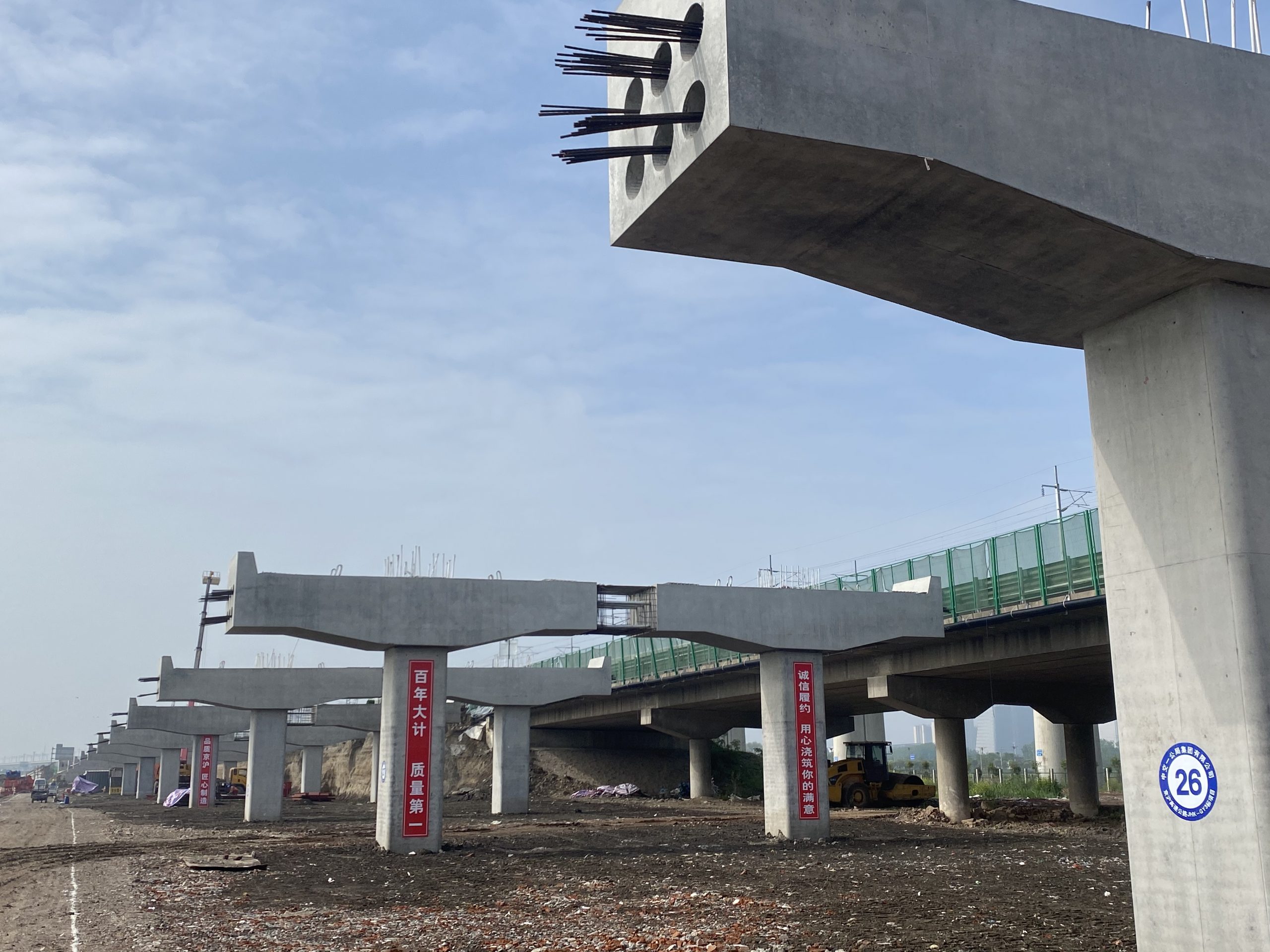
Construction of fabricated pier and abutment
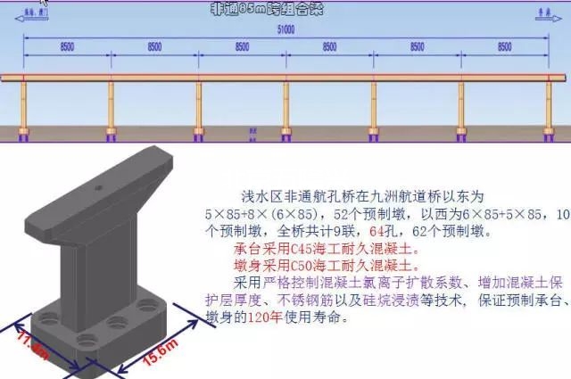
The fabricated pier and abutment is to divide the tall pier and abutment into several components vertically, according to a certain modulus and horizontally, pour on the Prefabrication Yard around the bridge site, transport it to the site by vehicle and ship, and hoist and assemble it.
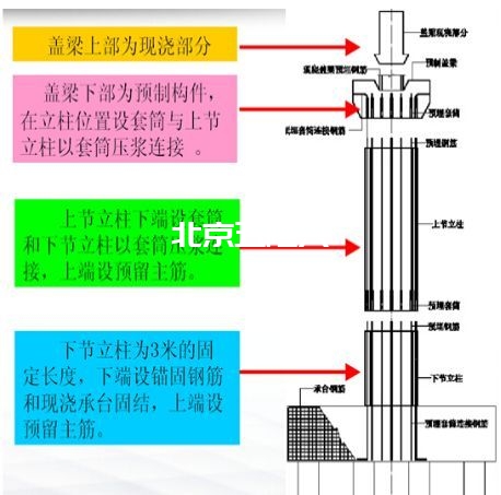
The main features of fabricated pier and abutment are:The components can be prefabricated in the Prefabrication Yard, which is less disturbed by the surrounding environment, but relatively speaking, it has high requirements for transportation and hoisting machinery and equipment. The fabricated column pier system decomposes the pier into several components, such as bearing platform, column, bent cap (pier cap), etc., which are prefabricated in the factory or on site, and then transported to the site for assembly into bridge pier. The construction process mainly includes prefabricated components, installation and connection and concrete joint filling. The assembly joint is the key process, which should be firm, safe, simple and convenient for construction.
Common assembly joints are as follows:
(1) Bonded post tensioned prestressed tendon connection structure is adopted
Bonded post tensioned prestressed reinforcement connection structure often cooperates with mortar cushion or epoxy adhesive joint structure to realize the construction of segmental Precast Pier. The prestressed reinforcement in the scheme can adopt high-strength reinforcement such as steel strand or finish rolled deformed steel bar. The structural feature is that the prestressed reinforcement passes through the joint, which is widely used in practical engineering, and the design theory, calculation analysis and construction technology experience are mature. The disadvantage is that the cost of the pier body is much higher than that of the traditional cast-in-situ concrete pier. At the same time, the on-site construction requires tensioning and grouting of the prestressed reinforcement. The construction process is complex and the construction time is long.
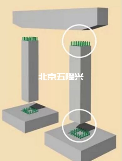
(2) Grouting sleeve connection
The precast pier body segments are connected with the protruding reinforcement through the grouting connecting sleeve. The contact surface between the pier body and the bent cap or bearing platform often adopts the mortar cushion, and the epoxy glue joint structure is adopted between the pier body segments. The structural characteristics are high construction accuracy requirements, short time required for on-site construction, and no tensioning of prestressed reinforcement. The on-site workload is significantly reduced. Its mechanical properties under normal service conditions are similar to those of traditional cast-in-situ concrete piers, so it has certain economic advantages. From the application experience abroad, low seismic risk areas have been widely used, and the application and scientific research of high seismic risk areas are still in progress.
(3) Grouted metal bellows connection
The connection structure is commonly used for the connection between the pier body and the cap or between the pier body and the cap. The prefabricated pier body connects the reinforcement protruding from the pier body through the grouting metal bellows embedded in the cap or cap. The mortar cushion is often used on the contact surface between the pier body and the cap or cap, and the epoxy adhesive joint structure is used between the segments of the pier body, as shown in Figure 5. The site construction time of this structure is short, but it needs to meet the sufficient anchorage length of longitudinal reinforcement, and its mechanical properties are similar to those of traditional cast-in-situ concrete piers. At present, a few bridges abroad have used this connection structure for construction, and it is rarely used in high earthquake risk areas. Its seismic performance is still under study.
(4) Slot connection
The slot connection structure is shown in Figure 6 and has been applied in some bridge projects. It is mainly used for the connection between pier body and bent cap, pile and bearing platform. Compared with grouting sleeve and metal bellows, it has the advantage that the required construction tolerance can be larger, and a certain amount of concrete needs to be poured on site.
(5) Reinforcement shall be welded or lapped and wet joints shall be adopted
A certain amount of reinforcement shall be extended in advance for the precast assembled pier to overlap with the reserved reinforcement of adjacent components, temporary support shall be set, and the reinforcement connection parts shall be connected by post cast concrete (wet joint), which is also the design idea of segmental assembled pier widely used in China. The mechanical properties of piers constructed with this structure are often similar to those of traditional cast-in-situ concrete piers, but the existence of wet joints will increase the construction time and the amount of on-site reinforcement lapping and pouring. From the perspective of rapid construction, this scheme has some deficiencies.
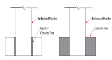
(6) Socket connection
The socket joint connection structure is to insert the precast pier body into the reserved hole corresponding to the foundation. The insertion length is generally 1.2 ~ 1.5 times the section size of the pier body. A certain thickness of mortar is laid at the bottom and filled with semi-dry concrete around. The advantages are simple construction process and less on-site operation; The deficiency is that the mechanical behavior of the joint, especially the seismic performance, needs to be further studied. Beijing Jishuitan bridge in China is built with this connection structure, and some bridges in the United States are also built with this connection structure. As shown in the figure.
Seismic performance of precast assembled columns
The seismic performance of prefabricated columns is a technical problem that hinders the application of full prefabrication and assembly technology in bridges in high seismic risk areas. In order to realize the comprehensive popularization and application of full prefabrication and assembly technology, the seismic performance of prefabricated columns must be deeply studied. Taking the typical actual engineering pier structure as the prototype, three precast assembly connection modes of sleeve, bellows and bonded prestressed reinforcement are selected to carry out the low cycle repeated horizontal loading scale test of rectangular solid segmental precast column. Through the pseudo-static test and finite element numerical analysis of segmental precast column specimens under different structural details, The hysteretic characteristics, ductile deformation, nonlinear mechanical behavior at joints, damage and failure mechanism of segmental precast columns under different structural modes are studied.
The test results show that compared with the traditional cast-in-situ concrete pier, the pier with sleeve and bellows prefabricated connection structure has similar seismic performance and can meet the requirements of expected seismic performance. The precast assembled pier connected with bonded prestressed tendons has the similar deformation capacity as the cast-in-situ concrete pier, but the energy dissipation capacity is weak. In addition, through calculation and analysis, connection device test and Research on the manufacturing and transportation process of the whole batch of specimens, it is shown that the two prefabricated assembly connection modes of sleeve and bellows, the overall stress, structural connection, seismic performance and the whole construction process details of the column can meet the current design and construction requirements and can be used in engineering practice.
The test results show that compared with the traditional cast-in-situ concrete pier, the pier with sleeve and bellows prefabricated connection structure has similar seismic performance and can meet the requirements of expected seismic performance. The precast assembled pier connected with bonded prestressed tendons has the similar deformation capacity as the cast-in-situ concrete pier, but the energy dissipation capacity is weak. In addition, through calculation and analysis, connection device test and Research on the manufacturing and transportation process of the whole batch of specimens, it is shown that the two prefabricated assembly connection modes of sleeve and bellows, the overall stress, structural connection, seismic performance and the whole construction process details of the column can meet the current design and construction requirements and can be used in engineering practice.
The following points shall be paid attention to in the construction of fabricated column pier and abutment:
(1) The pier and abutment column components and the reserved rod-shaped base on the top surface of the foundation shall be numbered, and the height of each pier and abutment and the coordinate height of the foundation shall be checked to see whether they meet the design requirements; The gap between the periphery of the foundation opening and the column edge shall not be less than 2cm.
(2) When the pier and abutment column is hoisted into the foundation cup and placed in place, it shall be measured in the longitudinal and transverse directions to make the column body verticality or inclination and plane position meet the design requirements; For the heavy and slender pier column, the hook can be placed only after it is fixed with wind cable or brace.
(3) Before installing the cap beam on the top of the pier and abutment column, check whether the position of the reserved slot hole on the cap beam meets the design requirements, otherwise it shall be repaired and chiseled first.
(4) After the column body and bent cap (pier cap) are installed and checked to meet the requirements, thin mortar can be poured at the gap between the base cup and the groove hole of the bent cap. After it is hardened, remove the wedge, support or wind cable, and then fill the wedge hole with mortar.
With the maturity and development of prestress technology, prestress began to be applied to piers and abutments, especially post tensioned prestressed reinforced concrete fabricated piers and abutments. Its construction method is similar to that of fabricated column pier and abutment. In addition to the connection joint treatment technology during installation, the connection mode between segmental precast members mainly depends on prestressed steel tendons.
The prestressed steel used for post tensioned prestressed reinforced concrete fabricated pier and abutment mainly includes high-strength low relaxation steel wire and cold drawn grade IV thick steel bar. The post tensioned prestressed reinforced concrete prefabricated pier and abutment can be tensioned in the following two ways: the tensioning position can be tensioned on the top of the pier cap; It can also be tensioned at the solid part of the pier and abutment bottom. Generally, the pier cap top is tensioned.
The prestressed steel used for post tensioned prestressed reinforced concrete fabricated pier and abutment mainly includes high-strength low relaxation steel wire and cold drawn grade IV thick steel bar. The post tensioned prestressed reinforced concrete prefabricated pier and abutment can be tensioned in the following two ways: the tensioning position can be tensioned on the top of the pier cap; It can also be tensioned at the solid part of the pier and abutment bottom. Generally, the pier cap top is tensioned.
(1) The main characteristics of tensioning prestressed steel tendon on the top of pier cap are as follows:
① The tensioning operators and equipment are working at height. Although the tensioning operation is convenient, the safety is poor;
② The anchorage end of prestressed steel tendon can be directly buried in the bearing platform without setting transition section;
③ At the position where the stress on the section at the pier bottom is the largest, the characteristics of strong bending resistance of prestressed steel tendon can be brought into play.
(2) The main characteristics of prestressed steel tendon tensioned by solid body at pier bottom are as follows:
① Tensioning operators and equipment are ground operation, safe and convenient;
② The transition section shall be set at the pier bottom, which shall not only meet the requirements for the placement of prestressed tendon tensioning jack, but also arrange more stress-bearing reinforcement to meet the stress requirements of the section in the operation stage;
③ The relationship between the tensioning position of prestressed tendon and vertical stressed reinforcement in transition members is complex. The tensioning requirements of prestressed tendon and grouting requirements in prestressed pipeline are consistent with the requirements of prestressed concrete beam.
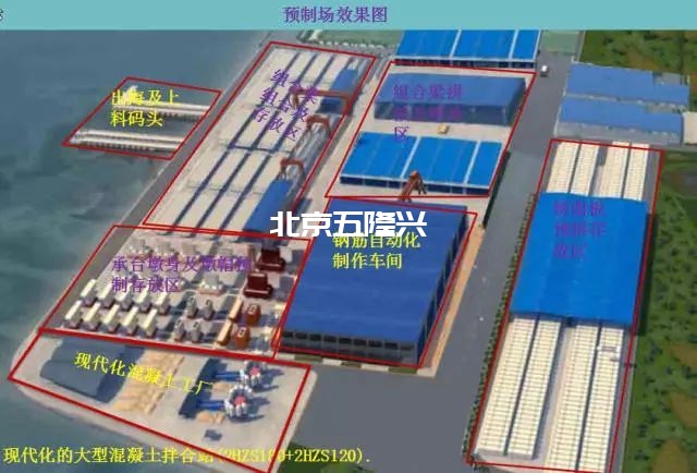
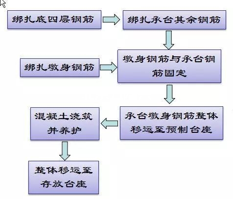
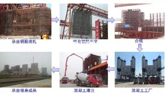
Prefabrication process flow
The total weight of the overall formwork truss system of the bearing platform and pier body is about 420t, which is designed with all steel formwork, which is mainly divided into four parts: formwork system, truss system, sliding system and adjustment system. Accurate positioning of the whole at one time.
Formwork system: bearing platform external formwork, bearing platform bottom formwork, pier body external formwork, bearing platform reserved hole formwork, pier body internal formwork and bearing platform top surface pressing formwork.
Truss system: bearing platform truss and pier body truss are supported on the sliding system.
Sliding system: slideway and sliding device.
Adjustment system: fine adjustment measures after the formwork is in place, including horizontal adjustment of Jack and wedge.
Truss system: bearing platform truss and pier body truss are supported on the sliding system.
Sliding system: slideway and sliding device.
Adjustment system: fine adjustment measures after the formwork is in place, including horizontal adjustment of Jack and wedge.
Concrete pouring of bearing platform and bottom section pier body
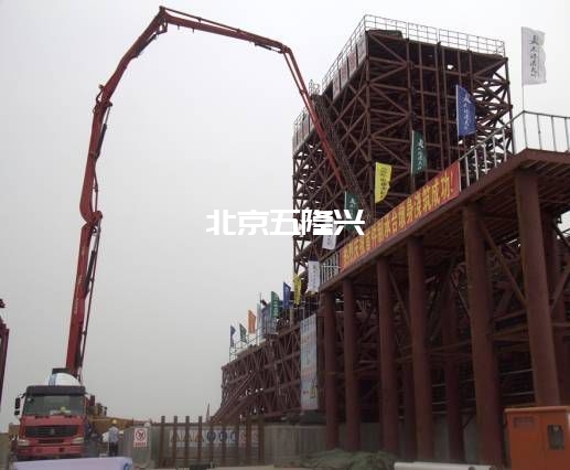
Formwork removal after concrete pouring of bearing platform and bottom section pier body
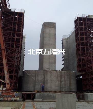
Fully prefabricated foundation by buried bed method:
A set of suspension system integrating hoisting, guiding, positioning and installation is adopted. In addition to the hoisting and suspension functions of prefabricated pier and abutment, the system also has the positioning functions including pier and abutment verticality, vertical elevation and in-plane position, and the positioning accuracy reaches 0.5mm.
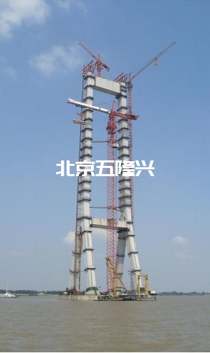
Cable tower construction
(1) Engineering difficulties
- The cable tower is high and flexible, which is easily affected by sunshine, temperature change and wind, and the linear control is difficult;
- The steel anchor box is used in the anchorage zone for the first time, with high accuracy requirements and great difficulty in construction control;
- The cable tower is high and far from the shore, and the measurement accuracy is difficult to ensure;
- There are many windy weather and few effective operation days.
(2) Key technology
Concrete cable tower control technology;
Steel anchor box installation control technology.
Steel anchor box installation control technology.
钢索塔
Steel beam cantilever construction
According to different lifting methods, suspension assembly can be divided into: floating crane suspension assembly, traction pulley block suspension assembly, continuous Jack suspension assembly, cable crane (cable crane) suspension assembly and cantilever crane. The core of cantilever assembly is the transportation and assembly of beams, and the prefabrication of beam segments is the basis of cantilever assembly. The suspension assembly construction process mainly includes prefabrication, displacement, storage and transportation of beam segments; Lifting and assembly of beam section; Transformation of cantilever beam system; Construction of closure section.
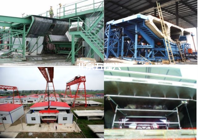
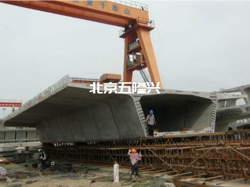
Concrete segmental beam construction
Precast segment (reinforced concrete segment and steel beam segment) assembly construction method: the beam body of the bridge is longitudinally divided into several segment blocks, prefabricated in the factory or in the Prefabrication Yard near the bridge site, transported to the bridge site, and then assembled into an integral structure by applying prestress. It is a construction method developed in recent 40 years and is widely used in the construction of reinforced concrete and steel bridges.
The prefabrication of segments mainly includes long line pedestal method and short line pedestal method
The long line pedestal method is to match and prefabricate all blocks one by one on a long pedestal according to the designed beam making line, so as to form a natural matching surface between the two blocks. The advantage of this method is that it is easy to control the geometry, and there is no accumulated deviation in the prefabrication process. The deviation of the fabricated block can be adjusted in time through the next block, and it can match the prefabrication at multiple points at the same time to speed up the construction progress. In addition, after demoulding the prefabricated components by this method, it is not necessary to transfer them to the storage place immediately.
However, this method also has the following shortcomings: ① large floor area; ② The pedestal must be built on a solid foundation. ③ Curved bridges also need to form the required curvature. ④ Pouring, curing and other equipment are mobile.
However, this method also has the following shortcomings: ① large floor area; ② The pedestal must be built on a solid foundation. ③ Curved bridges also need to form the required curvature. ④ Pouring, curing and other equipment are mobile.
The construction of short line pedestal method means that the pouring of each section is carried out in the same formwork, one end is a fixed formwork, and the other end is a section poured first. The length of the formwork is only the length of one section, and the formwork does not move, while the beam section is moved from the pouring position to the matching position and then transported to the beam storage yard. This method covers a small area, can form assembly line operation, improves the construction speed, and is suitable for engineering needs with more changes in section types and frequent formwork replacement. Its disadvantage is that the matching section must be placed very accurately, so it needs precise measuring instruments and equipment and accurate measurement and control methods.
Prefabrication of concrete segmental beam
Section beam handling: the lifting point for reasonable section handling shall be selected appropriately to control the section stress within the allowable range.
Stacking of segmental beams: the segments must be stacked in a way that can avoid warpage and secondary stress, and the floor can provide good support for the segments; The lower part of the web plate of the segment and the position close to the web plate shall be supported. During stacking, the weight of the upper segment shall be directly transmitted from the web plate to avoid bending and force transmission of the top and bottom plate.
Transportation of segmental beams: due to the large self weight of concrete beam segments, the precast yard of concrete beam segments is generally selected close to the bridge site and transported to the bridge site for assembly by tire transporter, beam carrier or beam rail car.
Segmental beam assembly
(1) Full support method:
(2) Less support method (mostly used for steel beams):
As the full support requires the treatment of the whole foundation under the bridge, the cost is large and the construction period is long. Therefore, when conditions permit, the segments are generally lengthened and the assembly construction is carried out in the form of less supports.
(3) Span by span assembly method:
The superstructure is erected in one direction, one span at a time. Before prestressing, the prestressing section shall be temporarily supported by the lower suspension beam (below the main beam) or the bridge erecting machine (above the main beam). The erected main beam can be simply supported on the pier, or several holes can be connected into a continuous structure through post tensioned prestress.
It is suitable for prestressed concrete simply supported beam bridge with small and medium span, all external and internal mixing, and continuous beam bridge with simply supported and continuous span by span. The construction method is mainly composed of a steel truss guide beam with a length less than (or greater than) twice the standard span length, lifting flat car, guide beam travel and adjustment, etc.
If the segments are assembled by hanging under the guide beam, the bridge erecting machine is called upper guide beam bridge erecting machine; If the segment is on the guide beam and assembled with support, the bridge erecting machine is called lower guide beam bridge erecting machine; The guide beam will bear the weight of one span precast segment.
(4) Balanced cantilever method:
The segments are assembled symmetrically with a pier as the center. Each segment is integrated with the previous installed segment, self balanced, and serves as the assembly basis of the next segment. For each construction step, the cantilever structure ensures its safety and stability by tensioning the prestressed steel tendon set in the box girder section. The hoisting of segments can be carried out by bridge deck support crane, guide beam or ground crane.
Suitable for cantilever construction, medium and long-span prestressed concrete bridge with internal and external mixing.
Suitable for cantilever construction, medium and long-span prestressed concrete bridge with internal and external mixing.
(5) Cantilever assembly method
The simple device moving on the cantilever of the assembled structure is used to ensure the segment lifting, translation and assembly; The lifting equipment is installed on the flat car, which runs on the bridge deck track.
Medium and long span bridges suitable for cantilever construction.
Medium and long span bridges suitable for cantilever construction.
(6) Cable hoisting method
Construction method for transporting and installing components by suspended cables.
It is generally applicable to the construction of arch rib or beam of arch bridge and main beam of suspension bridge.
It is generally applicable to the construction of arch rib or beam of arch bridge and main beam of suspension bridge.
Installation of external prestressing tendons: HDPE pipe is usually used as the outer sleeve of external prestressing steel strand bundle. In order to arrange the steel strand neatly in the outer sleeve and make it possible to adjust and replace a single steel strand, the method of single installation in sequence shall be adopted.
Adjustment and replacement of external prestressed reinforcement:
1) When the tension of external prestressed reinforcement needs to be adjusted, the protective cover can be removed, the anti-corrosion grease can be removed, the steel strand can be tensioned or relaxed with a special jack, and then the protective cover can be reinstalled and filled with anti-corrosion grease;
2) When the external prestressed reinforcement needs to be replaced, the new and old steel strands shall be connected with special connectors, the old steel strand shall be pulled out and the new steel strand shall be pulled in, and then tensioned, the protective cover shall be reinstalled and filled with anti-corrosion grease.
1) Dry joints without treatment;
2) Adhesive joints coated with epoxy resin;
3) Wet joints poured with cement concrete.
Wet joints are mainly used to close segments or connecting segments; Glue joints shall be used for internal and external mixed prestressed bridges and circulating freeze-thaw areas, and sealing washers shall be set before the pipe opening of internal prestressed reinforcement at the glue joint.


