 五隆兴科技发展有限公司

According to the pile diameter and geological conditions in the design drawings, the pile driver adopts gps15 type.
2)Survey and setting out
The survey and setting out shall be carried out according to the pile number provided in the design drawing, and the pile position shall be measured. The setting out shall be measured by the total station. The supervising engineer shall stand by during the survey. The survey results shall be recorded and the forming data shall be submitted to the supervising engineer for review and signature for approval.
3)Site preparation
The plane size of the drilling site shall be determined according to the plane size of the pile foundation design, the number of drilling rigs and the plane size of the drilling rig base, the drilling rig displacement requirements, the construction method and the layout of other construction equipment and facilities.
A.When the drilling ground is the ground, the site shall be leveled, sundries shall be removed, rammed and compacted, and a simple working platform shall be built.
B.The height of the water working platform shall consider the possible high water level during construction, and shall be 0.5 ~ 1.0m higher than its high water level. The distance between the wooden piles of the working platform is 1.5m (6m long and 16cm in diameter), which is arranged in parallel along the center line of the bored pile, the center distance is 1.5m, and the longitudinal cross section is 25 × 25cm2 square timber is used as guide timber, the wooden piles are fixedly connected, then the transverse guide timber is laid, and then two longitudinal guide timber are laid for the displacement of the drilling rig.
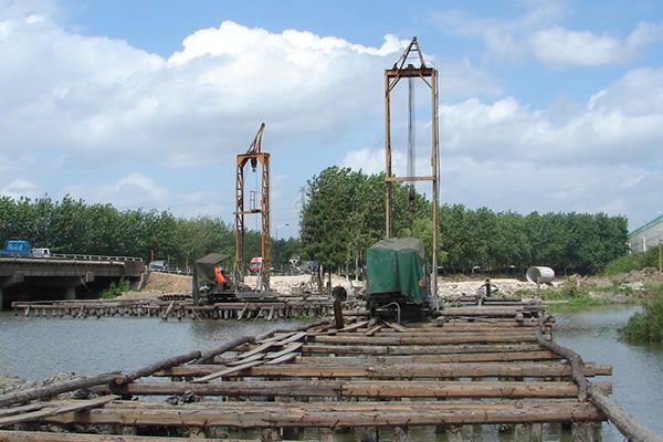
Figure: Water bent of bored cast-in-place pile
Casing fabrication requirements:
It is required to be firm, durable, not easy to deform, water tight, convenient for loading and unloading and reusable. The inner diameter of the casing shall be slightly larger than the design diameter of the bored pile. The casing shall be made of steel casing with flange, which is generally made of 3 ~ 5mm thick steel plate. In order to increase stiffness and prevent deformation, a stiffening rib can be welded on the outer sides of the upper, lower and middle parts of the pile casing, which can be made into an integral or two semicircles.
5)Rig up
The drilling frame shall be able to bear the weight of drilling tools and other auxiliary equipment, with good stability and certain stiffness. It will not move and shake during drilling or other operations. Its height shall be determined according to the length of drilling tools and the length of reinforcement skeleton joints, generally 8 ~ 12m.
When the drilling rig (frame) is installed in place, it shall be measured in detail, the base shall be padded and plugged with sleepers, the top shall be fixed stably with cable wind rope, and it shall be checked frequently during drilling to ensure that the rotary table surface is horizontal and the drilling rig frame is vertical, so as to ensure the verticality and hole diameter of the pile body.
After the pile frame is in place and aligned with the center of the pile position, the setting out shall be reviewed by the supervising engineer.
6)Making mud
During drilling, mud with a certain consistency shall be maintained in the hole. When drilling in a good clay layer, clean water can also be injected. When drilling, mud is made in the hole to achieve the effect of wall consolidation.
◆Inspection standard:
A.The central position deviation of pile position measurement shall be ≤ 5mm.
B.Requirements for embedded pile casing: the plane position of pile casing shall be buried correctly, and the deviation shall not be greater than 50mm. The elevation of pile casing top shall be 1.0 ~ 1.5m higher than the maximum construction water level.
C.The general specific gravity of mud should be 1.15 ~ 1.2.
(2)Drill hole
The sedimentation tank and water supply tank required by the drilling rig shall be set on the same side of the drainage outlet of the drilling rig, and the distance from the drilling rig can be determined according to the terrain. The total volume of the two tanks is generally 1.2 ~ 2.0 times of the total slag discharge volume after drilling.
1)Rig in place. Erect the drill frame, adjust and install the lifting system, lift the drill bit and put it into the casing. Start the winch to lift the rotary table, pad square timber under the rotary table base, level the drilling rig and align it with the drilling hole. Then install the rotary table, and the center of the rotary table shall be on the same plumb line as the lifting pulley on the drill frame. The position deviation of drill pipe shall not be greater than 2cm. The rotary table shall be checked frequently during drilling. If there is inclination or displacement, it shall be corrected in time.
Start the winch, lift the Kelly through the rotary table and connect it to the drill bit, install the square sleeve, clamp the Kelly and prepare for drilling.
2)Spud in. Before spud in, prepare mud with specific gravity of 1.15 ~ 1.2 and enter the mud pit and hole. Start the drilling rig to drill slowly. During drilling, check the mud specific gravity in time and control it between 1.2 and 1.3. The viscosity shall be controlled within 16 ~ 22 seconds. If any inconsistency is found, it shall be adjusted in time. If it is found that the terrain and geology are inconsistent with the provided data, contact the drilling and design units in time.
3)Lengthen the drill pipe. When a drill pipe is drilled, first stop the rotation of the rotary table and continue the operation of the circulating system until the sediment at the bottom of the hole is basically discharged (about 1 ~ 3 minutes), and then turn off the mud pump to extend the drill pipe. Place a 3 ~ 5mm thick rubber band between the joint flanges, and tighten the bolts to prevent air and water leakage. Then continue drilling after everything is normal as in the above process.
4)Control ROP: when drilling in hard clay, use the first gear speed to loosen the free footage of the hoisting wire rope. When drilling in ordinary clay and sandy clay, the second and third speeds can be used and the footage is free. When drilling in sandy soil or containing a small amount of pebbles, the first and second speeds should be used, and the footage should be controlled to avoid sinking the bit or failing to keep up with the speed of pumping drilling slag.
In case of silty sand with rich groundwater and easy to collapse, low-grade slow drilling should be used to reduce the agitation of bit on silty sand, increase the proportion of mud and increase the water head, so as to strengthen the wall protection and prevent hole collapse.

Figure: Measuring hole depth with measuring rope
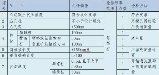
Table: Allowable deviation of cast-in-place pile
②In the table, l is the length of the column (mm). ③ D in the table is the diameter of the pile (mm).
A.Before cutting reinforcement, first be familiar with the design drawings and check the length and quantity of reinforcement of various specifications. At the same time, ensure the number of reinforcement required by the design.
B.The surface of the reinforcement shall be clean and free from damage. The oil stain, paint skin and scale embroidery on the surface shall be cleaned before use. The reinforcement with granular or flake old embroidery shall not be used; If there are serious pits and spots on the reinforcement surface after rust removal, and the section has been damaged, it shall be degraded or removed.
C.The spacing between the reinforcing bars of the reinforcement cage is 2m, which shall be welded on one side, and the weld shall not be less than 10d. It shall be set on the inner side of the main reinforcement, and the reinforcing stirrup shall be welded with the main reinforcement; Spiral reinforcement is outside the main reinforcement.
D.The pitch of spiral reinforcement within 10m of pile top is 10cm, and the rest is 20cm.
E.The main reinforcement of the reinforcement cage is mechanically connected, and the joint is connected with upsetting straight thread. The connecting joint of stressed reinforcement shall be set at the place with small internal force and staggered.
F.In order to ensure the thickness of reinforcement protective layer, the cushion block of reinforcement protective layer adopts round cake roller mortar cushion block. One group shall be set every 2m, and four in each group shall be evenly set around the pile foundation reinforcement.
G.For each pile, the acoustic pipe shall be arranged according to the positive triangle (three pieces) of pile diameter on the inner side of the reinforcement of the pile body, and the acoustic pipe shall be bound on the reinforcement cage with iron wire. Both ends are closed with steel plates to prevent mud and sundries from blocking the pipeline.
H.Appropriate measures shall be taken to prevent deformation of reinforcement framework during transportation.
◆Inspection standard:
A. Reinforcement of reinforcement cage shall be spot welded with main reinforcement, and spiral reinforcement shall be bound with main reinforcement; The welding length and quality of main reinforcement shall meet the design and specification requirements, and the joints shall be staggered. The rust, oil stain, mortar and other attachments adhered to the reinforcement shall be completely removed to avoid affecting its effect with the concrete.
B.The allowable error and inspection method of reinforcement cage fabrication shall comply with the provisions in the following table:
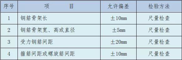
Figure: Allowable error and inspection method of reinforcement cage fabrication
After hole cleaning, the supervising engineer shall recheck the sediment thickness.


您好!请登录