 五隆兴科技发展有限公司
Foundation slab reinforcement binding
1、Construction process of foundation slab reinforcement binding:
1) Before binding the bottom slab reinforcement, calculate the number of reinforcement required for the bottom slab according to the reinforcement spacing required by the design, and set out the position line of the bottom slab reinforcement (including the position line of ground beam reinforcement) and the position line of wall column joint reinforcement on the cushion.
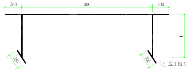
2) When binding the reinforcement of the bearing platform, the lower reinforcement of the bottom plate shall be laid first. According to the design and specification requirements, determine which direction of the lower reinforcement is below. Refer to page 66-70 of 16g101-1 for installation. After binding the lower reinforcement, set the reinforcement horse stool at an interval of about 0.8m. The horse stool and additional reinforcement shall be supported on the lower reinforcement net and shall not fall directly on the protective layer. Place the positioning reinforcement in both vertical and horizontal directions on the horse stool, The up-down sequence and binding method of reinforcement are the same as those of the lower reinforcement of the bottom plate. The height of the horse stool H = the height of the pile cap – the thickness of the concrete protective layer – the diameter of the two-way reinforcement in the upper layer – the diameter of the one-way reinforcement in the lower part. The pile cap is set with a spacing of about 800mm, as shown in the following figure:
2. Binding method of foundation slab
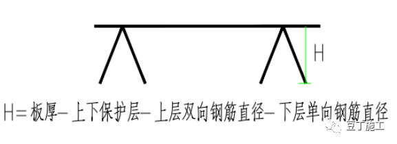
While binding the bottom plate, do a good job in binding the bottom plate beam, that is, first bind things first and then bind the reinforcement in the north-south direction. The joint position is “the lower iron is in the middle of the span and the upper iron is in the support”. The reinforcement joints at the beam slab foundation must be staggered by 50%, and shall be accurately discharged in strict accordance with the sequence and position of the batching list. The lower iron protective layer of the foundation slab is 40 (50) mm and the upper iron is 30mm. The upper and lower irons of the slab are supported by horse stool irons with a spacing of 800mm. The horse stool height = bottom plate thickness – upper and lower protective layers – upper two-way reinforcement diameter – lower one-way reinforcement diameter.
Stirrup is processed with 14 steel bars
3. Construction requirements for bottom plate reinforcement: the reinforcement shall be bound with full buckle, and the adjacent buckle shall be “eight” buckle, and the buckle head shall be bent into the inner side of the structural plate. Before binding reinforcement, the spacing line for reinforcement placement shall be snapped with ink line and bound according to the line. Before binding the upper reinforcement, the horse stool iron shall be arranged, and then the iron shall be bound.
4. The thickness of foundation base plate (damp proof plate) of the project is 350mm.
二、Column reinforcement binding
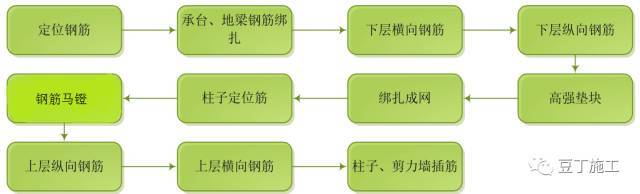
Process flow: snap the column line → chisel the laitance on the column concrete surface → repair the column reinforcement → set the column stirrup → install the vertical stress reinforcement → draw the stirrup spacing line → bind the stirrup → install the cushion block.
1. Calculate the number of stirrups for each column according to the spacing required by the drawing, and draw the stirrup spacing on the column reinforcement with chalk.
2. Set the stirrup from top to bottom and bind it with the main reinforcement. The stirrup shall be perpendicular to the main reinforcement, the intersection point of the stirrup corner and the main reinforcement shall be bound, and the intersection point of the non corner part of the main reinforcement and the stirrup shall also be bound. The joints of stirrups (i.e. the overlap of hooks) shall be staggered vertically along the column.
3. Protective layer of column reinforcement: plastic snap ring shall be used, which shall be clamped at the column corner according to the vertical spacing of 500mm, and the horizontal direction shall be set according to 400mm, so as to ensure the correct thickness of the protective layer of main reinforcement.
4. When binding the end column, it shall be noted that its anchorage must meet the requirements of design drawings and national standard 16g101.
5. At the junction of column and beam, the stirrup of column and the main reinforcement of beam shall be matched. After the main reinforcement of beam is threaded and bound, the column stirrup at this place shall be bound.
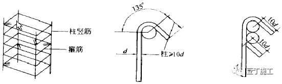
6. According to the seismic requirements, the end of column stirrup shall be bent to 135 °, and the length of straight part shall not be less than 10d (D is the diameter of stirrup).
7. The stirrup spacing at column base, column top and beam column junction shall be densified according to the design requirements. Stirrups at the upper and lower ends of the column shall be densified, and the length of the densified area and the spacing of stirrups in the densified area shall meet the requirements of the design drawings. If the design requires the stirrup to be provided with tie bar, the tie bar shall hook the stirrup, as shown in the figure:
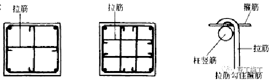
Layout diagram of tie bar
Plastic snap ring cushion blocks are preferred for columns, and the vertical and horizontal spacing shall not exceed 600mm. The protruding part of the tie bar of the brick wall shall be bent upward and close to the formwork. After the formwork is removed, it shall be removed before the brick wall is built; At least positioning support shall be set for column joint reinforcement, and the positioning support shall be welded with reinforcement.
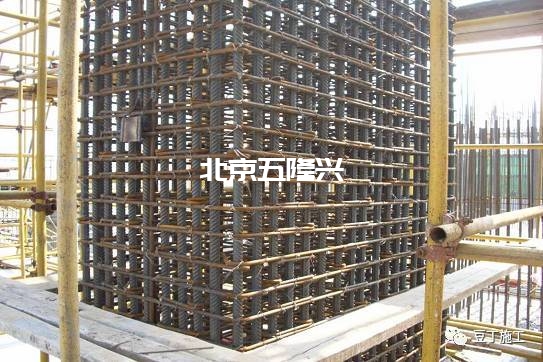
The binding effect diagram of frame column reinforcement is as follows:
Source: Douding construction, Baidu Library, for learning and sharing only.


