 五隆兴科技发展有限公司
Through this paper, we can clarify the process flow, operation points and corresponding process standards for the fabrication and installation of pile foundation reinforcement cage, and guide and standardize the construction of reinforcement cage.
1、 Preparation basis
Code for welding and acceptance of reinforcement (jgj18-2012)
Hot rolled plain steel bars for reinforced concrete (gb1499.1)
Hot rolled ribbed steel bars for reinforced concrete (gb1499.2)
Standard for quality inspection and evaluation of Highway Engineering (jtgf80 / 1-2004)
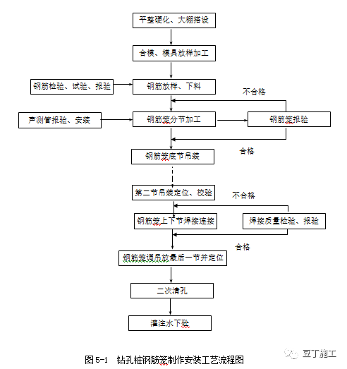
2、 Construction procedure
Raw material inspection → weldability test → welding parameter test → equipment inspection → construction preparation → mould making → reinforcement cage segmented processing → acoustic measurement and control installation → lifting of reinforcement cage bottom section → lifting of the second section → correction and connection → cyclic construction → positioning of the last section.
3、 Processing and fabrication of reinforcement cage
3.1 construction preparation
(1) The reinforcement processing site shall be hardened, and the raw material area, processing area and finished product storage area shall be planned and distinguished.
(2) Raw materials shall be mobilized, applied for inspection and used only after passing the test.
(3) Personnel and equipment organization, mobilization of reinforcement workers, welders and other personnel and reinforcement cutter, electric welder, straightener and other equipment.
(4) Set up power lines and configure transformers and generators according to the actual situation on site.
(5) Fabrication and processing of reinforcement cage mould.
3.2 reinforcement mobilization
(1) when entering the site, the reinforcement shall be provided with ex factory quality certificate and test report.
In addition to the appearance and marks, samples shall be taken in batches according to different steel types, grades, brands, specifications and manufacturers for mechanical property inspection. They can be used only after passing the inspection.
(2) reinforcement shall be protected from corrosion, pollution or bending during transportation. During storage, it shall be stacked neatly in batches according to different varieties and specifications, without mixing, and identification marks shall be set up. The storage time shall not exceed 6 months. The storage site shall be equipped with waterproof and drainage facilities, and the reinforcement shall not be directly placed on the ground, but shall be padded or stacked on the pedestal, and the top shall be covered with appropriate materials to prevent flooding and rain.
(3) the incoming reinforcement can be inspected in batches according to the reinforcement of the same brand, furnace and tank number, specification and size. Each 60t is a batch, and less than 60t is counted as a batch.
3.3 reinforcement processing
(1) rust removal
The surface of the reinforcement shall be clean and free from damage. The oil stain, paint skin and scale rust on the surface shall be removed before use. The reinforcement with granular or flake old rust shall not be used; When there are serious pits and spots on the reinforcement surface after rust removal, and the section has been damaged, it shall be degraded or removed.
(2) straightening
The reinforcement shall be straight without local bending, and the coiled reinforcement and bent reinforcement shall be straightened. When the cold drawing method is used to straighten the reinforcement, the cold drawing rate of r235 reinforcement shall not be greater than 2%; The cold drawing rate of HRB335 and HRB400 steel bars shall not be greater than 1%.
(3) blanking
The reinforcement shall be cut off according to the length required in the batching table, and the reinforcement with diameter less than 40mm can be cut by the reinforcement breaking machine; Those with diameter less than 12mm can be cut by grinder. When cutting, ensure the length accuracy of cutting material.
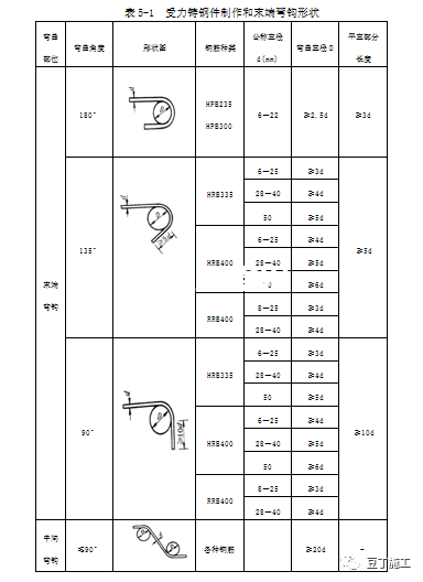
(4) bending forming
Bend and form according to the specifications and dimensions shown in the drawings and ingredient list, and the error shall be controlled according to Table 5-1.
(5) reinforcement lengthening generally, electric arc welding and flash butt welding can be used for the lengthening and welding of main reinforcement of reinforcement skeleton of pile foundation, and mechanical connection joints should be used for the connection of reinforcement skeleton of large-diameter pile and super long pile.
① Flash butt welding:
A. There shall be no transverse crack at the joint.
B. The reinforcement surface in contact with the electrode shall not have obvious burns to the reinforcement
C. The bending at the joint shall not be greater than 3 °.
D. The deviation of reinforcement axis at the joint shall not be greater than 0.1 times the reinforcement diameter, and shall not be greater than 2mm.
② Arc welding:
When overlapping or side bar arc welding is adopted for reinforcement joints, double-sided welds should be adopted.
When overlapping arc welding is adopted for the reinforcement joint, the overlapping ends of the two reinforcement shall be pre bent to make the axes of the two joint reinforcement consistent. When the upper bar arc welding is adopted for the reinforcement joint, the upper bar shall adopt the reinforcement of the same grade as the main reinforcement, and its total cross-sectional area shall not be less than the cross-sectional area of the welded reinforcement. The weld length shall be no less than 5B for double-sided weld and no less than 10d for single-sided weld. The distance between the arc welding joint and the bending of the reinforcement shall not be less than 10 times the diameter of the reinforcement, nor shall it be located at the maximum bending moment of the member.
The weld thickness of the welded joint shall not be less than 0.3 times the diameter of the main reinforcement; The weld width shall not be less than 0.8 times the diameter of the main reinforcement.
The appearance inspection results of arc welding joints shall meet the following requirements:
A. The weld surface shall be flat without depression or overlap;
B. There shall be no visible cracks in the welded joint area;
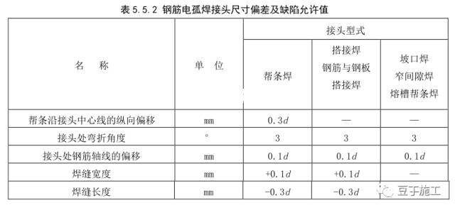
C. The allowable values of undercut depth, porosity, slag inclusion and other defects and the allowable deviation of joint size shall meet the requirements of table 5.5.2.
③ Mechanical joints:
The mechanical connection of reinforcement generally adopts upsetting straight thread, rolling straight thread or sleeve extrusion connection joint. Upsetting straight thread and rolling straight thread connection joints are applicable to HRB335 and HRB400 hot-rolled ribbed bars with diameter greater than or equal to 25mm; The sleeve extrusion joint is applicable to HRB335 and HRB400 hot-rolled ribbed bars with a diameter of 16 ~ 40mm. The minimum thickness of concrete cover at the mechanical connector of reinforcement shall meet the design requirements and shall not be less than 20mm, and the transverse clear distance between connectors or between connectors and reinforcement shall not be less than 25mm.
The position requirements for mechanical connection joints of stressed reinforcement are the same as those for welded joints.
After the mechanical joint connection and assembly of reinforcement is completed, it shall comply with the following provisions:
1. For upsetting straight thread connection joints, more than one complete thread shall not be exposed at each end of the sleeve. The exposed threads of extended screw head type, flared type and lock nut type joints are not subject to this restriction, but shall be clearly marked.
2. For the rolling straight thread connection joint, the effective thread shall be exposed outside the standard joint connection sleeve, and the effective thread exposed on one side of the positive and negative screw thread joint sleeve shall not exceed 2 times the pitch, and other connection forms shall meet the design requirements.
3. For the sleeve extrusion joint, the sleeve length after extrusion shall be 1.10 ~ 1.15 times of the original sleeve length, and the number of indentation passes shall meet the number of passes determined by type inspection.
④ Reinforcement joint location
For reinforcement joints, within 35d and not less than 500mm, the same reinforcement shall not have two joints. For the stressed reinforcement configured within the length of the joint, the percentage of the cross-sectional area of the joint in the total cross-sectional area shall not exceed 50% in the tensile area and unlimited in the compression area.
3.4 fabrication of reinforcement cage
(1) the reinforcement cage can be manufactured in whole or in sections according to the design length and equipment hoisting capacity. When sectional hoisting is adopted, trial assembly and butt joint shall be carried out in the processing plant first, and then hoisting shall be carried out separately to ensure the connection quality of butt reinforcement.
(2) the reinforcing bars shall be arranged according to the design requirements. The first reinforcing bar shall be 40cm away from the bottom of the bearing platform, the lowest one shall be 10cm above the bottom of the reinforcement, and the middle part shall be set every 2m from top to bottom. The zero number can be distributed in the bottom two sections, but shall not be greater than 2.5m.
(3) the reinforcement cage shall be manufactured on the special mould or bench. Before blanking, it must be straightened, then processed and blanking according to the number, and placed by classification and identification. The spacing of reinforcement must be fixed by at least two spacing fixed frames. Workers are not allowed to hold the fixed spacing by hand to ensure that the axis, smoothness and spacing of main reinforcement and stirrup meet the error requirements of design and specification.
(4) lifting points shall be evenly set at the upper end of the reinforcement cage, and the lifting points shall have sufficient strength and stiffness to ensure that the reinforcement cage will not be deformed during lifting.
(5) the reinforcement cage adopts concrete cushion blocks with the same grade as the pile concrete. The cushion block is 5cm thick, and a round hole is reserved in the center. 8 ~ 10mm reinforcement is penetrated in the round hole and welded and fixed on the main reinforcement. One circle of cushion blocks shall be symmetrically arranged every 2m vertically, and the upper and lower layers shall be staggered in quincunx shape, with no less than 4 in each circle, so as to ensure that the net protective layer of main reinforcement meets the design standard. After passing the acceptance, the concrete pouring construction shall be started.
3.5 storage, transportation and site hoisting of reinforcement framework
(1) the site for temporary storage of reinforcement framework must be flat and dry. The storage site adopts concrete hardened ground and is higher than the original ground, with sleepers under it and tarpaulin on it to avoid moisture or soil. Each section of each group of skeleton shall be sorted according to the pier pile number and section number, and signs shall be hung (such as the number of piers, the number of pile foundations, sections, length, whether they have been inspected, etc.), so as to facilitate loading and transportation in order when in use.
(2) the reinforcement skeleton must not be deformed during transportation to the pier. Strengthen the triangular support welded in the framework to strengthen its stiffness. When using automobile transportation, it is necessary to ensure that supporting points are set at each stiffener, and the height of each supporting point is equal; When manual lifting is adopted, more lifting rods shall be set, and the lifting rods shall be penetrated near the center of the skeleton as far as possible at the stiffener, and the stress of each lifting rod shall be as uniform as possible.
4、 Fabrication and installation of acoustic tube
According to the design requirements, the pile foundation requiring ultrasonic testing shall be equipped with acoustic testing pipe.
4.1 acoustic tube material
The acoustic pipe shall be steel pipe, with an internal aperture of no less than 50mm and a wall thickness of no less than 3.5mm. The quantity and layout shall be set evenly according to the design requirements.
4.2 acoustic tube processing
The acoustic pipe shall be pre installed on the formed reinforcement cage in the reinforcement cage manufacturing yard. The lower end of the acoustic pipe must be closed and the upper end covered to ensure that there is no foreign matter in the storage; The acoustic pipe shall be fixed with U-shaped reinforcement and binding double safety measures, which shall be firmly connected with the reinforcement cage (welding is not allowed); The connection of acoustic measuring pipe shall be actively carried out by external sleeve welding to prevent fracture or pipe blockage at the connection; The connection shall be smooth transition without water leakage; The pipe orifice shall be more than 100mm higher than the pile top, and the height of each acoustic pipe orifice shall be consistent.
4.3 forming of acoustic tube
The acoustic pipes after pile completion shall be vertical and parallel to each other, and blocking is strictly prohibited.
5、 Reinforcement cage installation
After the hole is formed, the first hole cleaning shall meet the standard, and the reinforcement cage installation shall be started after the verification and measurement are correct.
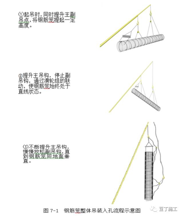
5.1 reinforcement cage hoisting
The reinforcement cage enters the hole and is hoisted by crane. The process is shown in Figure 7-1 “schematic diagram of overall hoisting process of reinforcement cage into hole”. When installing reinforcement cage, two-point hoisting shall be adopted. The first lifting point is set at the upper part of the skeleton and lifted with the hook of the crane. The second lifting point is set at the lower third point of the skeleton, and the small hook of the crane is used. The whole reinforcement cage shall be lifted at the same time and erected in the air for adjustment. When the diameter of the reinforcement cage is greater than 1200mm and the length is greater than 6m, the lifting point shall be strengthened, the stirrup at the lifting point shall be appropriately increased, and the welding quality shall be controlled to ensure that the reinforcement cage will not deform or fall off during lifting. When the reinforcement cage is hoisted into the hole, it shall be aligned with the hole diameter and kept vertical. It shall be placed gently and slowly into the hole. It shall be lowered slowly after entering the hole. It is not allowed to rotate left and right. It is strictly prohibited to swing and collide with the hole wall. In case of obstruction, the delegation shall be stopped, and the causes shall be found out for treatment. It is strictly prohibited to lift and drop and force to lower.
5.2 reinforcement cage connection
When the first section of skeleton is placed at the position of the last section of stiffener, the section steel shall be penetrated, the reinforcement skeleton shall be temporarily supported on the orifice section steel, and then the second section of skeleton shall be lifted to connect with the first section of skeleton. During connection, the position of the upper and lower main reinforcement shall be aligned, and the upper and lower axes of the reinforcement cage shall be kept in a straight line without turning. When connecting, first connect two joints in one direction, and then lift it slightly to make the upper and lower reinforcement cages vertical under the action of self weight, and then connect all other joints. The joint position must be staggered up and down according to 50% of the number of joints for at least 35d. After the joint is connected, bind the stirrup, lift the skeleton, pull out the supporting section steel, and lower the skeleton. In this way, the skeleton is lowered to the design elevation.
5.3 reinforcement cage fixing
The center of the reinforcement cage is aligned with the design center of the pile. The length of the positioning bar at the uppermost end of the skeleton must be calculated from the design pile top elevation and the measured pile casing elevation. After checking the skeleton center and elevation, it can be lifted and placed on the section steel set on the pile casing, or it can be directly welded on the pile casing or frame. In order to prevent the reinforcement cage from falling off or floating during pouring, the positioning reinforcement must be reinforced. After the reinforcement cage is positioned, concrete shall be poured within 6h to prevent hole collapse.
5.4 deviation requirements for reinforcement cage hoisting
(1) the deviation between the center of reinforcement cage and the center of pile hole shall not be greater than 10mm (measured by cross pile tension line);
(2) the elevation deviation of the bottom of the reinforcement cage shall not be greater than ± 50mm (measured by measuring rope and weight hammer).
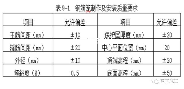
6、 Quality inspection standard
Quality requirements for fabrication and installation of reinforcement cage (table 9-1)
7、 Common quality problems and preventive measures
7.1 reinforcement cage deformation
(1) cause analysis:
① The reinforcement cage section is too long, the setting of reinforcing hoop is insufficient, and the stiffness is not enough;
② The reinforcement cage did not strictly comply with the technical regulations during stacking, transportation and hoisting, resulting in cumulative deformation.
(2) preventive measures:
① When the reinforcement cage is too long, it shall be fabricated and hoisted in sections, and then welded at the orifice;
② The reinforcing hoop shall be set according to the requirements of the technical specification and firmly welded with the main reinforcement;
③ When installing the reinforcement cage, it is advisable to set up a temporary lifting shoulder beam to increase the stiffness.
7.2 installation position deviation of reinforcement cage
(1) cause analysis:
① No cushion block is set on the reinforcement cage or the cushion block is insufficient, which can not effectively control the thickness of concrete protective layer;
② The pile hole itself has large deviation;
③ The reinforcement cage is not vertically hoisted into the hole, but obliquely inserted into the hole.
(2) preventive measures:
① A group of cushion blocks shall be set on the main reinforcement of the reinforcement cage at a certain distance to control the thickness of the concrete protective layer and align the plane position of the reinforcement cage with the hole axis;
② The reinforcement cage shall be hoisted into the cage in a vertical state.
7.3 floating of reinforcement cage
(1) cause analysis:
① When the concrete enters the bottom of the reinforcement cage, the pouring speed is too fast, the conduit is buried too deep, and it is jacked up by the concrete;
② The reinforcement cage is not fixed, and the reinforcement cage is hung when lifting the conduit.
(2) preventive measures:
① When the concrete rises close to the lower end of the reinforcement cage, the pouring speed shall be slowed down to reduce the rising kinetic energy of the concrete surface, so as to prevent the reinforcement cage from floating by jacking. When the reinforcement cage is buried in the concrete to a certain depth, lift the conduit to reduce the buried depth of the conduit, so that the lower end of the conduit is higher than the reinforcement cage is buried in the concrete to a certain depth. Yes, lift the conduit to reduce the buried depth of the conduit, and then pour at the normal speed when the lower end of the conduit is a considerable distance higher than the lower end of the reinforcement cage, which can prevent the reinforcement cage from floating upward under normal circumstances;
② Before pouring concrete, the reinforcement cage shall be fixed on the pile casing at the hole position to prevent floating.
The article comes from the Internet and is invaded and deleted.


